Use Case Diagram. A Simple Visualization of Use Cases.
What are use case diagrams? How are they created and what advantages do they offer?
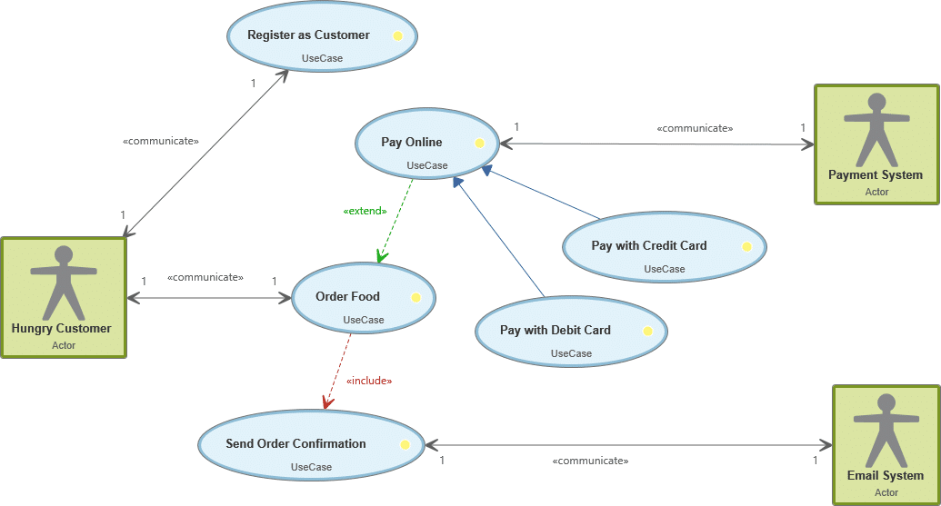
Use case diagrams visualize use cases or multiple actors and relationships between the use cases. In this example, the use case diagram describes an app for ordering food online.
The hungry customer plays the role of an actor that causes multiple use cases. Actors can also be objects like an email system. The 1 represents the multiplicity, which means that exactly one actor is participating in the use case.
Different relationships between actors and use cases can control the different relationships that a use case diagram presents with special arrows and descriptions.
Use case diagrams visualize use cases of one or more actors and relationships between use cases.
“Actually, we had something completely different in mind.” Not a sentence that you want to hear from a customer. But it happens. Because reality always shows us how different people communicate differently, or misunderstand things – Paul Watzlawick, the Austrian-American communication scientist, sends his greetings. When requirements in your software are misunderstood, imprecisely communicated or just not mentioned by the customer, that doesn’t just lead to uncomfortable conflict, it also costs you time and money. That is why use cases and use case diagrams have proven themselves in project management: a graphic visualization of the behavior of a system from the view of the user, described through defined visual means of UML (Unified Modeling Language). They offer great support when finding and defining requirements.
Use Case Diagram: a Short Definition
A use case diagram is a behavior diagram and visualizes the observable interactions between actors and the system under development. The diagram consists of the system, the related use cases and actors and relates these to each other:
System: What is being described?
Actor: Who is using the system?
Use Case: What are the actors doing?
What Is Not a Use Case Diagram?
A use case diagram doesn’t describe the order in which the use cases are carried out. For example, let’s define the use case Withdraw money. This process is carried out in many steps, like Insert card, Enter PIN, Select amount, take out amount and take card out. Of course, these are activities are all from the customer’s point of view – but this sequence should not be covered by the use case diagram. Other diagrams are recommended for that, like the activity diagram. A use case diagram should describe the desired functionality of the system and relates it to use cases and actors. That way it can represent existing viewpoints of the system and how they are interpreted differently – only through this can requirements be completely understood.
How Is a Use Case Diagram Created?
The system frames the use cases. The actors are outside of the system.
The Actor in a Use Case Diagram
Stick figures are the established way of representing actors. Although they are presented as people, actors don’t necessarily represent people – they can also represent non-human elements, like an email system. An actor can be both an active user of the system and trigger use cases that way, or passively used by the system to enable the realization of use cases. When an actor is defined, it always has to be related to at least one use case. An actor represents a role and can therefore be occupied by multiple people or systems. If multiple actors are participating in a use case, then this is expressed through multiplicity. It will be one by default. To describe actors as specifically as possible, it is also recommended to connect them with personas.
Overview of the Properties of the Actor:
- is human or non-human
- represents roles
- can specify multiplicity
- communicates with the system (connected to at least one use case)
- uses the system (triggers use cases)
- is used by the system (to realize use cases)
The Use Case in a Use Case Diagram
Use cases are normally presented as ovals. A use case represents a functionality of the system from the viewpoint of the user and describes the goals of their use. Here, the order of the action can and should be entered – for example Insert card, Enter PIN, etc – to cover alternative courses. If a use case is only detailed through another use case, then it is known as abstract and is identified thus in the use case. A multiplicity can also be entered for a use case. It describes how often a use case may be carried our. Often, use cases are very extensive – too extensive for agile projects that have to be implemented in a sprint in a couple of weeks. For this, the idea of Use Case 2.0 was developed.
Read more about Use Cases here »
Read more about Use Cases 2.0 here »
Overview of the Properties of the Use Case:
- describes the behavior of the system under development
- represents the perspectives of the user
- can specify multiplicity
- doesn’t consider the details of the system behavior
- can be abstract (not feasible itself, only through other use cases)
How To Create Use Case Diagrams Easily in Practice
Learn more about Requirements Modeling
with objectiF RPM or objectiF RM »

How Are Actors and Use Cases Related in a Use Case Diagram?
Association in the Use Case Diagram
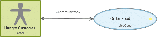
If an actor is involved in a use case – by starting a function of the system, for example – then this is controlled by a communication relationship, also called an association. It is identified in the use case diagram through a simple line or a line with arrows at both ends.
Include Relationship in the Use Case Diagram
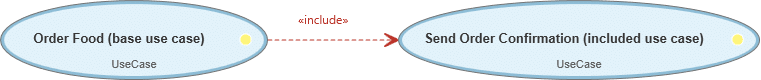
The include relationship always arises between use cases. It connects a use case (base use case) with one or more included use cases. That means: a use case needs another use case, the included use case, to be able to make its functionality available in the system. However, the included use case can be carried out separately. The include relationship is identified in a use case diagram with a dotted arrow with the label include. The arrow always points towards the included use case.
Extend Relationship in the Use Case Diagram
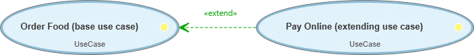
The extend relationship connects a use case with one or more use cases. The functionality of the extended use case can (but doesn’t have to) be integrated in a base use case – so the use case expands its functionality to the base case. The base use case decides whether the expanded use case will be carried out. Both use cases can be carried out separately. The use case’s expand relationship is presented in a use case diagram through a dotted arrow with the label extend. The arrow always points to the base use case.
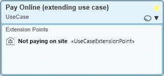
The point in time at which the behavior of a use case can be extended is the extension point. A use case can have multiple such extension points. They will be shown within the use case.
Generalization Relationship in the Use Case Diagram
A generalization relationship (also called an “is a type” relationship) can arise between actors and between use cases. In this relationship, the communication relationship is transferred: a generally described use case or actor takes over the communication relationship of the precisely-defined use cases or actors. These special cases allow the connection of use cases that only apply to them and not to generally described actors or use cases. The generalization relationship is presented through an arrow in the use case diagram that points towards the generally described use case or actor.
… between use cases
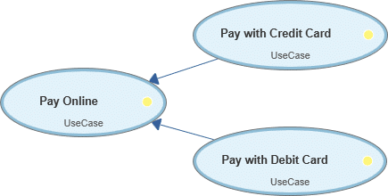
A generalization relationship between use cases controls if you define a general use case (use case A) that is specified through one or more use cases (use case B).
Use case A passes on its relationship(s) to the specified use case B. B needs A, can complete or overwrite A, and inherits all the relationships of A. Use case B finally decides what will be carried out by use case A.
For example, there is the use case Pay online. How can the system user pay online? Credit or debit card. Then specify these more precise payment methods in a use case diagram. (Use cases B and C).
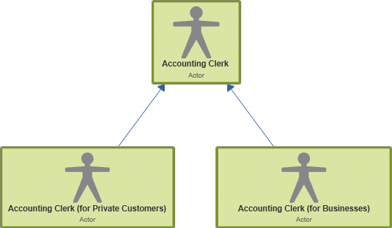
… between actors
A generalization relationship between actors controls when different actors are defined but have the same properties. Then one general actors is defined (Actor A) that points to the two actors.
The specialized actors can then take over at least the roles of the general actors.
For example, there might be a Accounting clerk (private) (Actor B) and an Accounting clerk (business) (Actor C). Both have properties that they share. So a general actor Accounting clerk (Actor A) can be defined that points to B and C.

Advantages of Use Case Diagrams
Use case diagrams are a outstanding means of:
Considering the system from the user's viewpoint,
getting different angles on the system and the requirements,
deriving recommended requirements,
deriving test cases,
and through all, developing the right system for users.
Use the advantages of use case diagrams
Use cases give you an overview of your system that forms the ideal foundation for finding and defining your requirements. Because with them you can place yourself in the position of your users better and find solutions to their problems. Use a tool with which you can easily create use cases and connect them with actors and other use cases in a diagram. Define communication relationships, generalization relationships and include and exclude relationships through clear visual means or specify the expansion points of a use case. And if you want to connect personas with actors or create test cases for use cases, you can even integrate them into your use case diagram. That way you have everything at a glance.