What Characterizes SysML 2?
How does it contribute to improving system development?
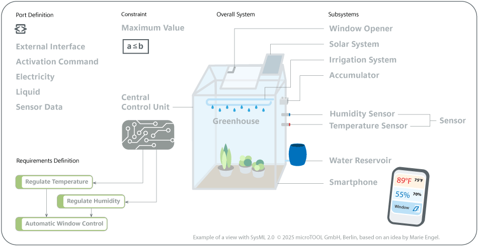
Elements of the Overall System
Definition-Usage System: A requirement definition can be used more than once for different requirements.
The greenhouse is the model of the entire automated system for cultivating climate-dependent plants. It also forms the boundary of all modeled functions, subsystems, and interfaces.
Subsystems can be viewed individually
The central control unit processes sensor data and applies decision logic to regulate environmental conditions. It also coordinates all connected subsystems and communicates with smartphones.
SysML 2 (Systems Modeling Language 2) is the latest version of the standardized modeling language for technical systems. Developed by the Object Management Group (OMG), it expands the capabilities of SysML 1.x and adapts the language to modern system engineering requirements.
How Is SysML 2 Defined?
SysML 2.0 is the next-generation systems modeling language offering significant improvements in precision, expressiveness, usability, interoperability, and extensibility over SysML 1.0. SysML 2 is used to specify requirements, behavior, structure, analysis, and verification, ensuring consistency and traceability across all aspects of the system model.
Source: Object Management Group (OMG).
“SysML 2.0 is the next-generation systems modeling language …”
Object Management Group (OMG)
How Was SysML 2 Developed?
The first version, SysML 1.0, was released in 2007 and is based on the Unified Modeling Language (UML). It supplements UML with concepts for modeling technical systems, such as requirements and block diagrams. However, in practical application, it became apparent that SysML 1.x was highly complex and inconsistent in its terminology. It also had limited interoperability between tools.
Against this backdrop, the Object Management Group (OMG) initiated the development of a new version. The goal was to create a more formally precise and semantically consistent language that could be used independently of platforms and tools. The beta version of SysML 2.0 was released in April 2024. Simultaneously, the first pilot implementations were made available, including integration into Plant UML and as a Jupyter notebook implementation.
What Are the Differences between SysML 2 and SysML 1.x?
One of the goals of developing SysML 2 was to simplify the modeling process. A key change was switching from UML to KerML (Kernel Modeling Language) as the semantic basis.
KerML is an application-independent metamodeling language that was standardized by the Object Management Group (OMG). It defines an abstract syntax and formal semantics for modeling systems and is based on mathematical logic.
The KerML core can be used for different modeling languages by extending it with specific language constructs.

Since KerML is not tied to object-oriented programming, it can simplify access for users without a computer science background. At the same time, it retains essential concepts, such as dependencies, ensuring conceptual proximity to existing approaches.

The definition-usage principle, introduced in SysML 2, distinguishes between the definition of a model element and how it is used in a specific context.
This allows systems and subsystems to be modeled as part definitions and used in different contexts via part usages. This separation enables consistent referencing and facilitates reuse.
The new standardized textual notation makes it easier to exchange models between different tools and enables teams to collaborate. Models can be exported, imported, and reused in development or testing environments.
Additionally, it allows for the automated generation or analysis of system models using large language models (LLMs), for example. However, since SysML 2 is still in the beta phase, limited training data is currently available for such applications.

The term “diagram type” is no longer used in SysML 2. The rigid diagram types that were adopted from UML have been replaced by “views,” which are now defined as model elements.
General View
The General View offers a flexible, configurable overview of model elements. It serves as a starting point for combining different pieces of information from a model, such as requirements, blocks, and relationships.
With the filter and selection mechanisms, you can display only the relevant model elements for a specific issue.
Thus, the General View is not limited to a specific diagram type; it can combine different types of elements and their relationships into a uniform view as needed.

Example of a view in SysML 2.0 [1]
Interconnection View
The Interconnection View corresponds to the Internal Block Diagram (IBD) in SysML 1.x and shows a system’s internal structure, including its subsystems and their relationships.
The composition of a system from its components and the type of coupling, such as physical interfaces, signal lines, or logical relationships, are modeled by it.
The Interconnection View is useful for analyzing component interactions within a system and for visualizing communication and dependency relationships.

Example of an internal block diagram [2]
The view concept allows models to be filtered and tailored specifically for different stakeholder groups. This is achieved by defining viewpoints, filter criteria, and display rules. Although this approach is more flexible than the fixed diagram types in SysML 1.x, it requires additional modeling steps.

Application in objectiF RPM and objectiF RM
SysML 1 is integrated into both objectiF RM and objectiF RPM. This means that key SysML principles, such as consistent modeling, traceability, and reuse, can be used and implemented in practice in model-based systems engineering already.
SysML 2 will be integrated soon. This will create ideal conditions for making model-based systems engineering more powerful and interoperable. In the future, models can be used more effectively across systems and evaluated automatically. This will allow for more transparent mapping of complex system relationships.